Final Project Ideas
This is a tracking page, so it captures my ideas, documents the progress on the final project while at the same time capturign changes and transitions in my ideas.Initial thoughts
A key idea that has intrigued me for a while is that given matter, energy and a set of instructions, we can create anything from anything (within second law limits. Additive manufacturing is one step in this direction - we take some raw materials (usually limited to 2 or 3 materials ahving fairly similar physical properties) and energy, usually in ther form of thermal (FDM) or electro-magnetic (SLA) and coupled with a set of instructions (G-code) we can create complex objects.
Along similar lines, I would like to create a system that can take materials with varying physical properties (as a starting point) and create integrated parts. My preliminary idea for this is to use insulators and conductors - plastic and metal, that can be used to create circuits and maybe even simple components like a parallel plate capacitor, such as the one sketched here.
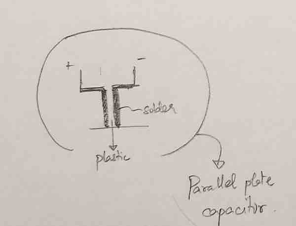
Integrated circuitry within typical thermo-plastic prints

In this example I've sketched how one might design a battery holder along with integrated wires or connections that can be secured to a LED to form a simple circuit.
In the below picture a similar circuit with a AAA battery and a simple motor is sketched

Update
So as I was going through the past few weekly assignments, I realised I could better scope my project and make something that is usable (as opposed to just the drive mechnaism for the above idea)
In the electronics production week I realised that it can be challenging to get smooth, shiny solder joints, so I started wondering if I could desing a smart solder pen that
integrates the temprature sensing and the actual deposition of the solder at the deisred location.
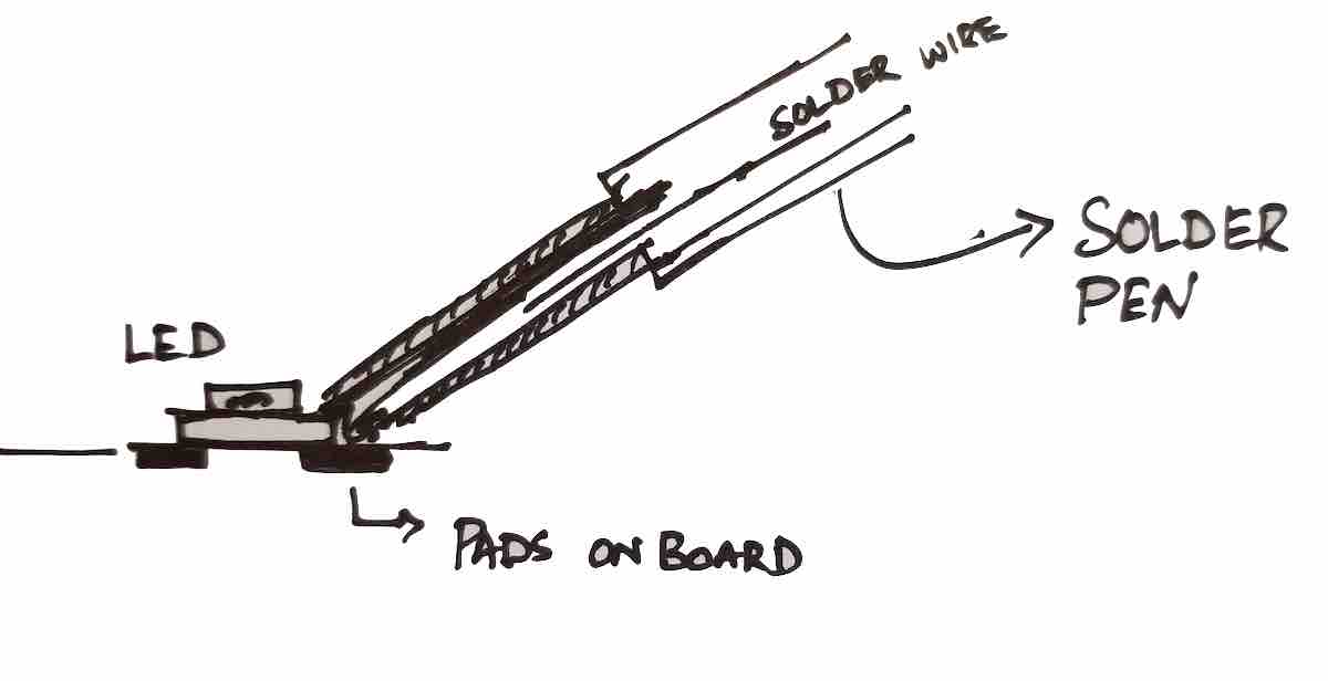 The adjacent image here shows what this might look like. You have a solder pen that has the solder wire inside it, a positioning "claw" at the tip that helps hold on to
components and temperature sensors at the tip that can sense when the pads/component connections are heated enough to avoid cold joints.
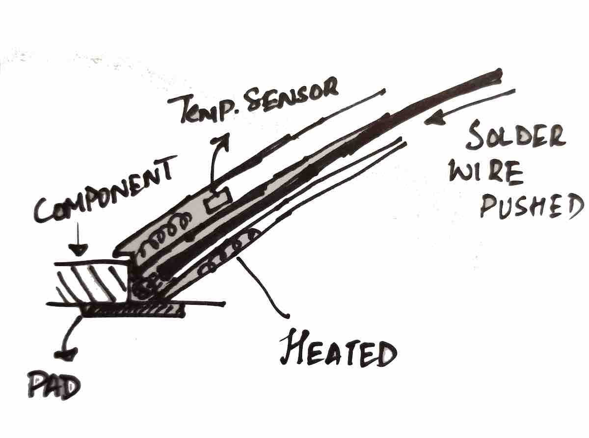 In the close up drawing you can see how the claw holds on to the component and when the temperature is right signals the user to press a button which the forces the solder wire thorugh to be deposited to form the joint. A second beep or flash signals the user to remove the soldering pen.
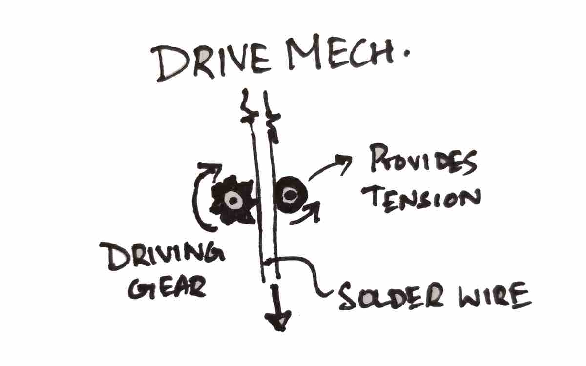 The drive mechancism can be pretty straightforward as shown in the drawing. It could be a simple gear that is driven by a motor and a tensioning bearing.
The solder wire would be squished between the two such that it can be pused by the motor driven gear.
Update 2
So I realised I really don't like solder that much, and I like making things that I can use in my day-to-day life, like the cool bookrack or the laptop stand I made.
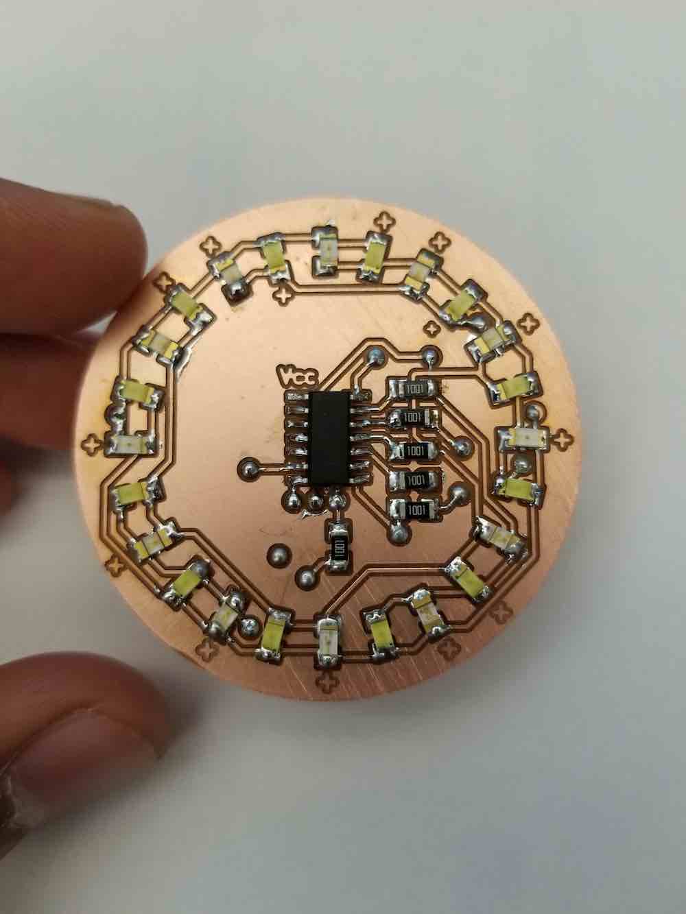
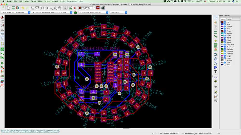 So I'm thinking about making a smart watch that I can use, inspired by previous project done in the class.
I really like an "analog" display so I thought it would be cool to use an LED array to show the time (different brightnesses/ or bliking to diffirentiate between the hr, min and s).
I've started practicing/ prototyping as you can see in Week 10. More updates will follow here! Stay tuned!