assignment
Now that we've had decent practice in designing and producing custom PCB hardware, we need to learn how to write code for our PCBs! This week, we were tasked with programming our board to do something.
the first blink | |
|
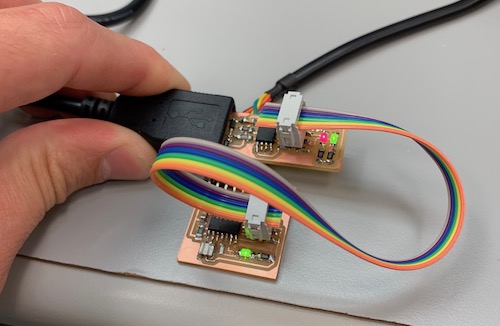
Just as a reminder, I created a simple board with an LED and a button a few weeks ago, allowing to program a board with basic input and output. I had realized that I messed up the button and had the button connect a pin on the board straight to Vcc. But, when the button wasn't pressed, the pin was connected to... nothing? So my first board didn't allow great sensing of input. But the LED worked fine! So I first started by making a few modest adjustments to the provided hello world program. I had to first mark the LED pin as an output, and then I added some logic to write a high voltage to that pin. |

|
int main(void) {
    // ...
    DDRA |= ~(1<<PA7);
    // ...
    PORTA |= (1<<PA7);
}
This sets the bit that controls the output voltage of the LED pin, making the led light up! |
|
the three-button board | |
|
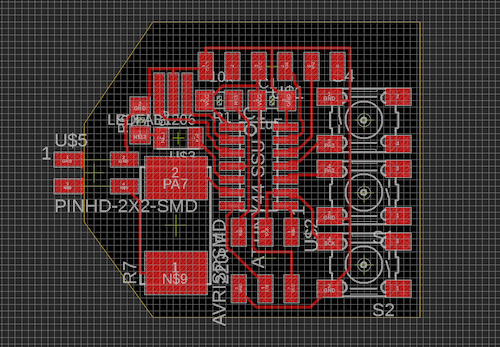
To make up for my single broken button, I decided to design a board that had three buttons! The initial hope was that with three buttons, I can represent 0-7 in binary, making up the 8 notes of a scale. To get started on my final project, it would be great to get an on-chip synthesizer working. As you could expect, routing this was a huge pain. I spent a lot of time with Eagle to route this week and really hate a few things about it. For example, to move a component, you have to click perfectly on the tiny target in the center of the component, and if there's a routed trace in that same spot, good luck... I may try KiCad in future weeks. |
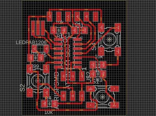
The design for the 3-button board. 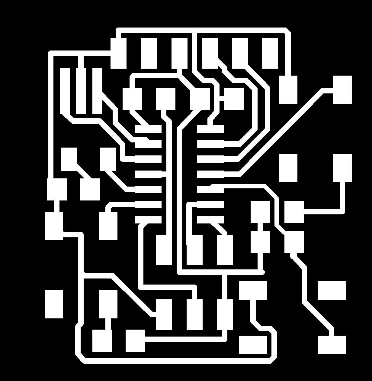
And the traces. |
|
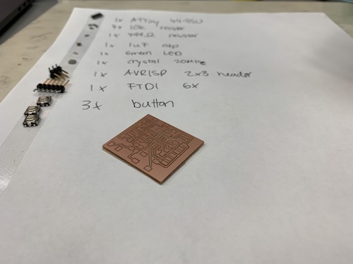
This board was ready, and I got to cutting, stuffing, and programming the board! I decided to learn to use the Other Mill this week, and it was surprisingly less difficult that I had anticipated. |
Cutting on the Other Mill. 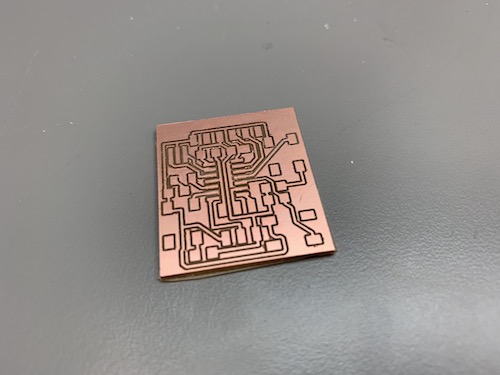
|
|
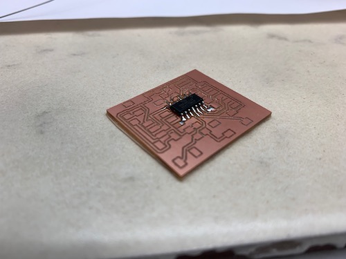
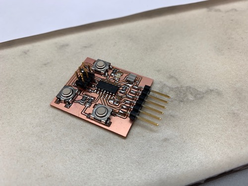
After lifting traces off two boards last week trying to make a new programmer, I was really intimidated going into stuffing these boards. I realized I had ended up using WAY too much solder - really a small dab is all that's needed for these tiny components. I would regularly solder two traces together on accident, and while desoldering, would lift traces. |
|
|
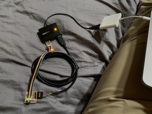
I had also ordered my own FTDI cable and slow USB 2.0 hub off Amazon to allow me to program from the comfort of my own home. |
|
|
I first wanted to master reading the input from 3 different buttons and composing an index from 0-7, so I decided to write a little (ugly and rushed) program that changed how fast the LED blinked depending on the number represented by button presses.
#define PIN_LED PB2
#define PIN_BTN1 PA7
#define PIN_BTN2 PA3
#define PIN_BTN3 PA2

#define DIGIWRITE_H(port, pin) port |= (1 << pin)
#define DIGIWRITE_L(port, pin) port &= ~(1 << pin)
#define PRESSED(pin) ((PINA & (1 << pin)) == 0)

int main(void) {
    // set clock divider to /1
    CLKPR = (1 << CLKPCE);
    CLKPR = (0 << CLKPS3) | (0 << CLKPS2) | (0 << CLKPS1) | (0 << CLKPS0);

    DDRB |= (1 << PIN_LED);
    DDRA &= (0 << PIN_BTN1);
    DDRA &= (0 << PIN_BTN2);
    DDRA &= (0 << PIN_BTN3);

    DIGIWRITE_H(PORTB, PIN_LED);
    while (1) {
        uint8_t input = 0;
        input |= PRESSED(PIN_BTN1) << 0;
        input |= PRESSED(PIN_BTN2) << 1;
        input |= PRESSED(PIN_BTN3) << 2;
        DIGIWRITE_L(PORTB, PIN_LED);
        switch (input) {
            case 0: _delay_ms(0); break;
            case 1: _delay_ms(100); break;
            case 2: _delay_ms(200); break;
            case 3: _delay_ms(300); break;
            case 4: _delay_ms(400); break;
            case 5: _delay_ms(500); break;
            case 6: _delay_ms(600); break;
            case 7: _delay_ms(700); break;
        }
        DIGIWRITE_H(PORTB, PIN_LED);
        _delay_ms(100);
    }
    return 0;
}
| |
the speaker board | |
|
My initial plan to make a synthesizer was to get this board spit out the value of a sine wave to my laptop over serial and then parse and play the sine wave off my laptop. I then realized that I couldn't easily print to the provided terminal script over serial, so decided to just make a new board with a speaker on it! |
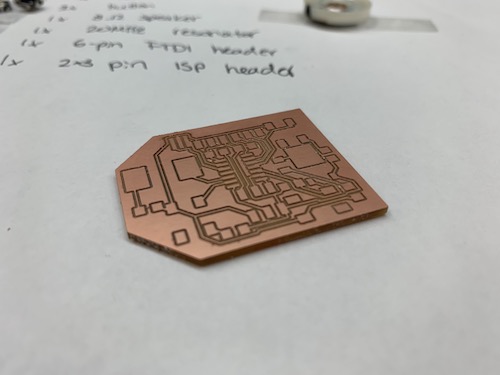
The newly cut out board with a slot to attach a removeable speaker |
|
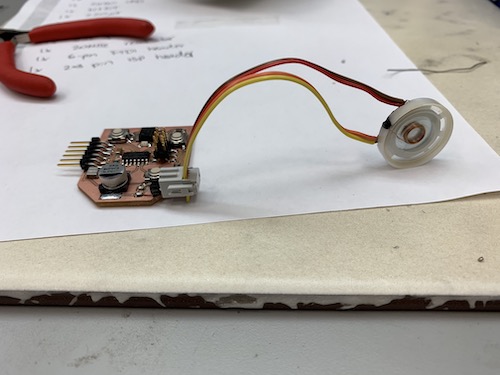
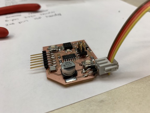
Since the speaker was too large to be soldered onto the board, I decided to design a board with a port for a removeable speaker. I soldered a ribbon cable to the speaker and added a 2-pin ISP header to the board. The ribbon cable is attached to a 4-pin female header. |
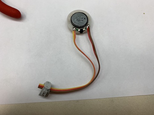
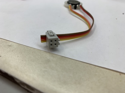
|
|
This allows the speaker to plug in and out nicely. |
|
|
With this, I got started trying to program the board. I had found an example of waveform generation on an ATtiny. After trying to adapt it for the ATtiny44, I realized the example was made for the ATtiny85. Now, I was forced to learn and read the ATtiny44 data sheet and try to figure out how to get the PWM working, which allows outputting values on a digital pin that appear to be analog, allowing outputing the decimal range of a sine wave. |
|
|
But when reading the data sheet, I realized that I had connected the speaker to a pin incapable of performing PWM... Since I had to redesign the board, I saved this for another time. |
|