assignment
Now that we have our own in-circuit programmer, we are free to create our own boards and program them.
|
To get accustomed to this process, we were tasked with extending a basic programmable board that could keep track of time, the hello-world board: To build on this basic functionality, I added both an LED for output and button for input into unused pins, milled this board, and programmed it! |

|
design | |
|
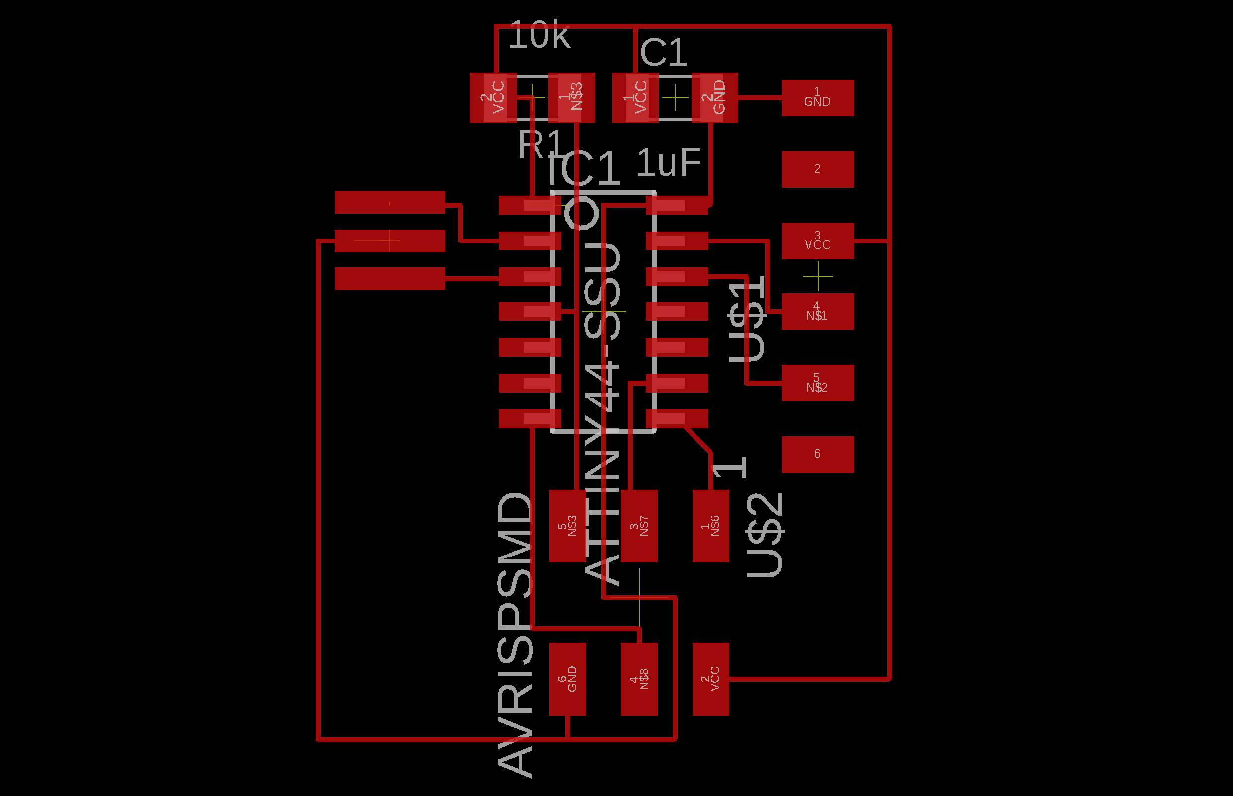
To begin, I reconstructed the hello world board from scratch using Eagle, an industry standard for PCB design. The interface is decently clunky and clearly made for hardware designers - for example, instead of being able to select a large component by clicking anywhere on it, you have to click precisely on handle point made for that component. After figuring out the kinks of Eagle, I created a close replica of the hello world board. |
|
|
Then, I planned how to include the new components. For output, I planned that a high voltage on some pin should light up the LED. So, I connected an LED and current-limiting resistor to ground from an unused pin on the microcontroller, so a high voltage on the output would cause current to run through the LED and light it up! For input, I figured a high voltage into a pin should signal that the switch is turned on, so I used a switch to connect Vcc to another unused pin and found homes for these new components. |
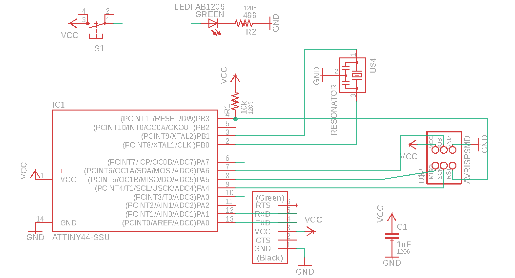
The schematic of my board design. |
|
Now, I had to route this new design, placing the components purposefully to prevent traces from crossing. board schematic |
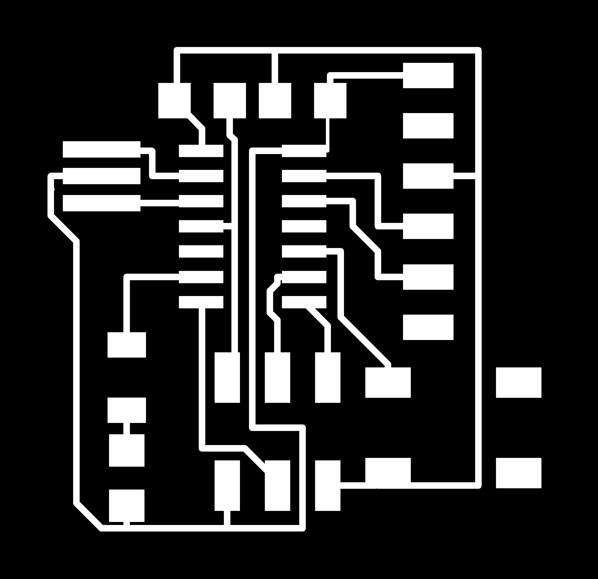
Board traces 
Board cut |
|
After milling everything out, I began to solder! I had forgotten how small these components were... |
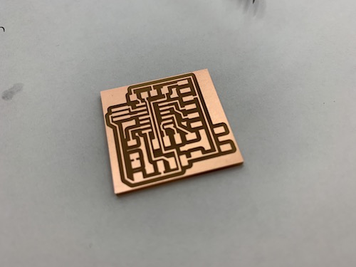
The milled out board 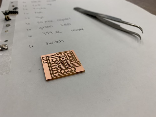
Preparing to solder! 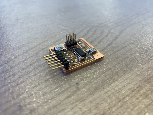
The soldered board! |
|
I somehow mustered up the fine-grained motor control needed to stuff the board, and then it was time to start programming! |

|