Why do objects look the way they do? Why does a basketball
look round, while the moon looks like a flat disk? If white
objects supposedly reflect all light, why don't white-painted
walls look like mirrors?
And when we see pictures taken with scanning electron beams, why
is it so easy to interpret them as landscapes and artifacts? Why
is it so much harder to see what's going on under a standard light
microscope?
The answer is that different materials reflect radiation in
different ways. In our daily life, we come across several
different familiar types of materials and lighting
conditions. For example:
Smooth, specular surfaces (like mirrors) faithfully
transmit incoming light into a similar outgoing direction.
Rough, matte surfaces (like painted walls) scatter
incoming light in all directions, regardless of the direction
it originated from.
And of course there are less familiar materials and lighting
conditions:
The moon (like the rocky planets) is
covered in a dust which scatters light in a way which is very
different from either the matte or glossy surfaces in our
daily life. As a result, the moon has different shading than
we'd expect for round objects of ordinary materials—
it's not that the moon is far away, it's that it's scattering
light in a uniform way that we've only seen for flat
surfaces. We therefore interpret the moon as flat.
Under a light microscope, we see a world
of translucent objects suspended in transparent medium. This
world is very unlike our macroscopic world which is filled
of opaque surfaces in a transparent medium (air).
Figuring out how translucent objects are arranged in space
(tomography) is fundamentally a much harder problem
than figuring out how opaque objects are arranged in space
— there are fewer depth cues to tell how far away
objects are.
In this sense, we humans are lucky not to have
“x-ray vision” — if we did, we would be able to see
through many more objects, and the resulting translucent
world could be much more difficult to figure out.
Under a scanning electron microscope, we see a
world of unusual artifacts and vistas— but we can easily
interpret the shapes and relative locations in these images. The
reason is that even though we are shining electrons instead of
photons on these objects, the resulting pictures are shaded
in ways that we recognize, and so they give us cues as to how their
scenes are laid out.
Minnaert's reflectance family
The astronomer Marcel Minnaert invented a family of functions that
captures the reflectance behaviors of materials as diverse as paint,
moondust, and objects viewed under an electron microscope.
The function models how radiation (e.g. visible light or electrons)
impinging on a surface from one direction gets transmitted in another
direction, based on the material the surface is made of.
It's a function relating four variables, giving
the radiance (officially, the energy flux per
foreshortened area per solid angle) emitted in a
particular emission angle based on the energy coming
in from the incident angle, as a result of
the surface material.
The function is:
$$L = \frac{k+1}{2\pi}[\cos{\theta_i}]^{k}\cdot [\cos{\theta_e}]^{k-1}$$
where \(L\) is the radiance, \(\theta_i\) and \(\theta_e\) are the
angles at which the light is incoming and emitted relative to the
surface normal direction, and \(k\) is a parameter that encodes
something about the material and lighting conditions.
The important benchmarks for the material constant \(k\) are:
When \(k=1\), the surface behaves like an ideal matte surface
under ordinary light — like a painted wall. This reflectance
behavior is called Lambertian
When \(k=\frac{1}{2}\), the surface behaves like moondust under
ordinary sunlight. This reflectance behavior is
called Hapke-like.
When \(k=0\), the surface behaves like an object being imaged
under a scanning electron microscope, where a conducting ring boils
off electrons in a focused beam to create an image. The resulting
images are interpretable but have a strangely inverted illumination
pattern: surfaces viewed head-on appear darker than
surfaces viewed from the side.
A four-variable nomogram for Minnaert's reflectance family
Here, I've plotted Minnaert's reflectance family as an oriented
nomogram with transparency. (For details, see some of
the other nomograms of this type which I've
made.)
This nomogram relates radiance, incident and emitted angles, and the
surface parameter. You can use this nomogram to solve for any one
parameter given the other three, and also to see qualitatively how the
parameters affect each other.
For example, to solve for radiance given the other three parameters:
On the vertical axis, locate the material
parameter \(k\). Click and drag the teal (radiance) axis to
that height.
At the top of the nomogram, locate the dark curve corresponding
to the cosine of the incident angle.
At the bottom of the nomogram, locate the red curve
corresponding to the cosine of the emission
angle.
Follow the two curves until they reach the height of the teal
(radiance) axis.
The horizontal separation between the two curves corresponds to
the radiance. We can use the transparent movable overlay to
determine the radiance quantitatively.
Slide the teal (radiance) axis left or right until the red
calibration dot is on the grey incident angle curve.
Find where the teal scale intersects the red emitted angle
curve. Read off the teal scale's value at that point.
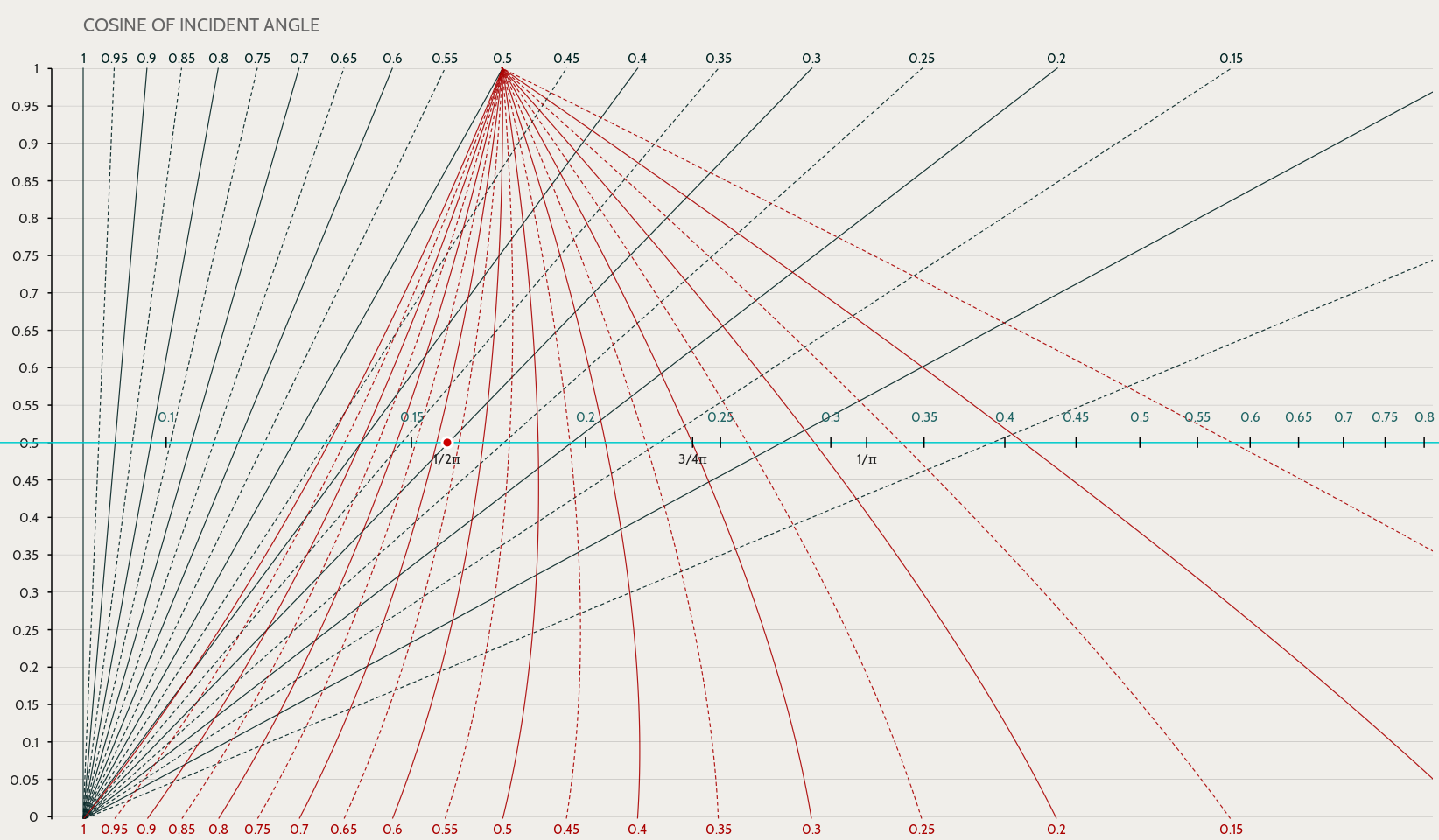
For example, the following picture shows how to find the radiance
given \(k=0.5\) and the incident and emitted angles both have a cosine
of 0.3. First, you find the material parameter on the vertical axis
(0.5). Next, you drag the teal (radiance) axis to that height. Third,
you find the grey curve corresponding to the incident angle (0.3), and
the red curve corresponding to the emitted angle (0.3). Follow those
curves to where they meet the teal (radiance) axis.
Fourth, you slide the teal scale until the red calibration dot is over
the grey incident angle curve, as shown. Fifth, you find where the
teal axis meets the red curve. Reading off the teal scale at that
point, you solve for the luminance: it is 3/(4π), or around 0.23.
As for qualitative trends, you can explore the following:
When \(k=1\), the surface is Lambertian (like matte paint). You
can see that here the radiance does not depend on the angle of
emitted light, i.e. the viewing angle; it appears equally bright
from all emission directions.
When \(k=\frac{1}{2}\), the surface is Hapke-like (like the moon
or a rocky planet). If you look carefully, you can see that the
radiance has the same value whenever the incident and emitted angles
are equal.
Finally, when \(k=0\), the surface behaves as if illuminated by a
scanning electron beam. Note that radiance does not depend on the
direction of incoming light. Note also that strangely, the surface
gets brighter as the emission angle (the viewing angle) gets smaller
and smaller — this kind of surface looks brighter viewed in
profile than when viewed head-on.
For more information, see Prof. Berthold Horn's detail-rich
textbook Robot Vision, which uses physical models to
find closed-form analytic and/or computationally inexpensive
solutions to problems in vision.
 For example, the following picture shows how to find the radiance
given \(k=0.5\) and the incident and emitted angles both have a cosine
of 0.3. First, you find the material parameter on the vertical axis
(0.5). Next, you drag the teal (radiance) axis to that height. Third,
you find the grey curve corresponding to the incident angle (0.3), and
the red curve corresponding to the emitted angle (0.3). Follow those
curves to where they meet the teal (radiance) axis.
Fourth, you slide the teal scale until the red calibration dot is over
the grey incident angle curve, as shown. Fifth, you find where the
teal axis meets the red curve. Reading off the teal scale at that
point, you solve for the luminance: it is 3/(4π), or around 0.23.
As for qualitative trends, you can explore the following:
For example, the following picture shows how to find the radiance
given \(k=0.5\) and the incident and emitted angles both have a cosine
of 0.3. First, you find the material parameter on the vertical axis
(0.5). Next, you drag the teal (radiance) axis to that height. Third,
you find the grey curve corresponding to the incident angle (0.3), and
the red curve corresponding to the emitted angle (0.3). Follow those
curves to where they meet the teal (radiance) axis.
Fourth, you slide the teal scale until the red calibration dot is over
the grey incident angle curve, as shown. Fifth, you find where the
teal axis meets the red curve. Reading off the teal scale at that
point, you solve for the luminance: it is 3/(4π), or around 0.23.
As for qualitative trends, you can explore the following:
