 Solid-state relay
This week's assignment is to add an ouput to a designed microcontroller board. Since I'm now thinking mainly about my final project, I have split this assignment into two parts: (i) Clapper switch for my amplifier; (ii) speakers for my future DAC board, which I will start assembling this week.
For my input device , I have used the relay as an output (to switch the tube amplifier for my final project)
 Solid-state relay
Solid state relay is a great tool to control high power/voltage equipment with low voltage logic signals. Though I eventually plan to use this circuit for turning my tube amplifier on, the amplifier is currently at the development stage, so I instead plugged in the christmas lights to the relay.
Christmas lights turned with a clapper
One can see that the circuit works as required, though there is a slight leakage in the "off" state, which one can recognize from the dimmed (rather than the turned off) lights.
To start the DAC board, I had to go through the Hello world experience, which wasted much more time then I expected. A great introduction to the XMegas can be found in the Jake's page.
I have used the Jake's DAC board for the purpose of Hello world. Regardless of the original purpose of the code, I have found it very handy even for my own DAC project, since it can help very quickly diagnose if my own newly designed board works or not. I have milled his board, stuffed it, and after struggling for quite some time with the software side, I have managed to succesfully load the code to the XMega board.
 Successful test of freshly milled XMega board
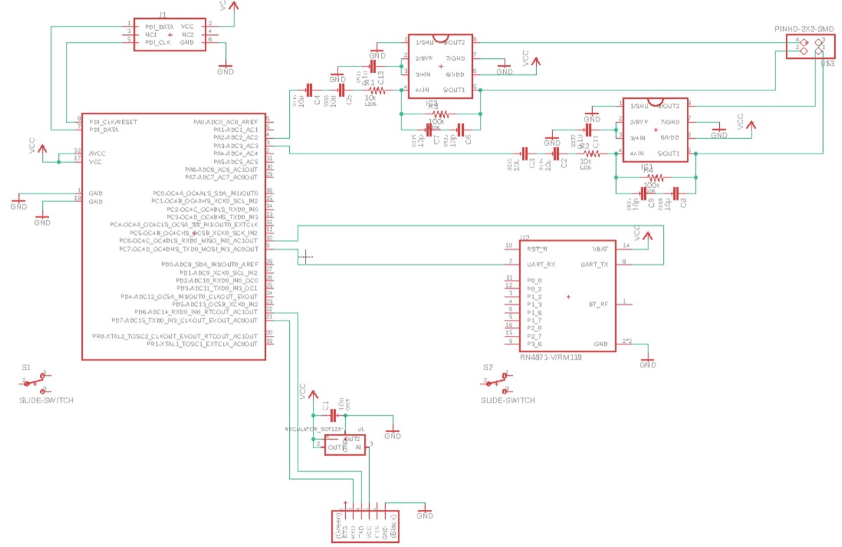
The next step was to design my own board. At that point, I had very little time left and managed only to pick the right components and draft the circuit design, consisting of XMega, Op-amps and the Bluetooth module:
 Initial sketch of the DAC + pre-amplifier
The continuation of this work can be found below: