motivation
After prototyping a 16-pad multitouch board, it was time to build a bigger multitouch board with enough pads for the entire neck a guitar.
I was initially planning to use multiple 16-pad boards powered by ATTiny44s. After manufacturing one, I realized how painful and tedious this was, and I didn't particularly want to get six microcontrollers talking to each other. So, I turned to the ATMega! It turns out that the microcontroller had exactly enough pins to create twelve frets for six strings, a decently sized guitar. I also decided that I would send this off to a boardhouse to reduce production time.
design | |
|
The 72-pad board is mostly the same as the smaller, 16-pad board: each touch pad is modeled as a capacitor, and touching the pad changes the capacitance. The pads are on the reverse side of the board. Since I had a terrible time routing the last multitouch board I created, I preemptively added zero-ohm jumpers to the grid of touchpads to allow for a more mechanical and patterned routing. After shipping the boards off to a boardhouse, I realized I could have made use of the reverse side of the board in between the pads... |

|
|
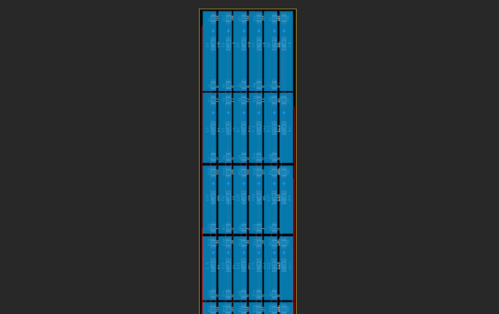
This time, I had to create the touchpads in the same dimensions as frets on a guitar, so I took out a measuring tape and immitated my own guitar. |
|
|
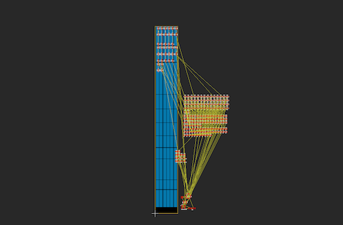
This led to a huge mess of components that needed to be placed... |
|
|
But after placing, I was able to make good use of the autorouter! The boardhouse's way looser design rules (6mil clearance, 6mil traces) made routing a lot better than with our self-produced boards. | |
|
Here's the final result! The board files can be found here. 
After exploring a few boardhouses, I ended up using JLCPCB. The boards arrived in less than a week and were decently affordable compared to other options. | |
stuffing | |
|
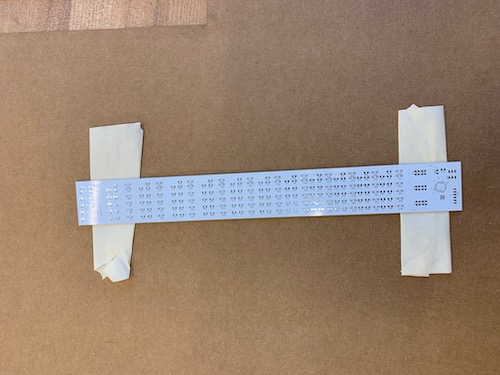
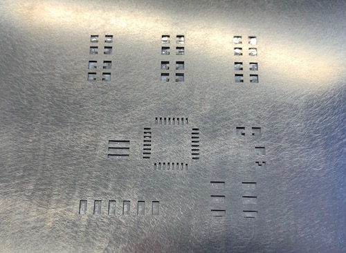
I ordered a stencil along with my board to make stuffing 240 components a lot easier on myself... I first taped down the board to be stuffed to keep it stationary, and then I lined up the stencil on top of the board and taped down the stencil for a secure fit. |
|
|
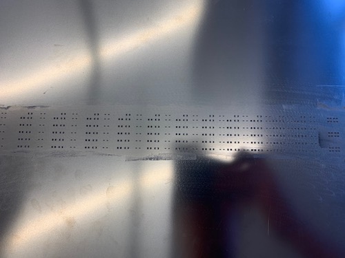
I very crudely spread the solder paste into the holes of the stencil; it wasn't very artful as the tutorial I had watched, but it got the job done. |
|
|
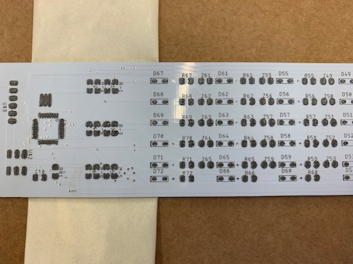
The solder paste had bridged pads very close to each other, so I scraped away some of the excess with tweezers. However, I later learned that the solder paste really shrinks when it's reflowed, so there likely wouldn't have been any solder bridges even if I didn't clear away the excess. |
|
|
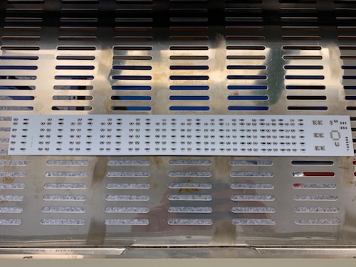
Even though it took me about an hour just to place the components, it was surely faster than individually soldering components. Would recommend! |
|
|
I ran into a little scare that I had used the wrong microcontroller footprint: turns out, there's a big difference between the ATMega328p and the ATMega16U2 - make sure to read up on your data sheets! I saved the programming for interface programming week. | |
| Next > | |