assignment
Just as it sounds, we were tasked with making and programming a board with an output device. I had already started dabbling with speakers in week 6, so I continued where I left off!
board fabrication | |
|
After becoming more acquianted with microcontroller data sheets, I realized that not all pins are capable of outputting a PWM wave... so, I redesigned the board I had made in week 6, also using the internal pull up resistors for buttons instead of external ones. |


|
|
This new board was a ton more compact than the last few. |
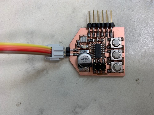
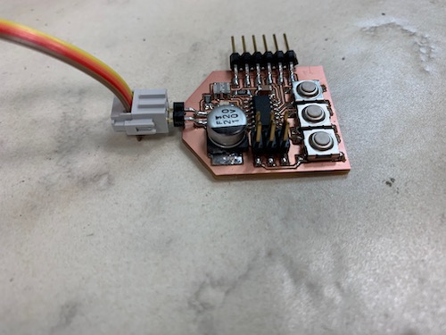
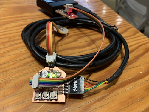
|
|
I've now made quite the progression of boards. |
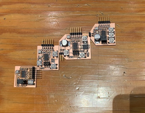
|
programming | |
|
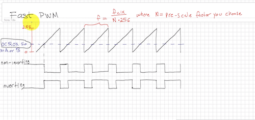
I've done a bit of sound synthesis before so was familiar enough with the idea of wavetable synthesis. The hard part was getting PWM to work on the microcontroller. I found a nice YouTube tutorial explaining how to use the PWM pins, and this diagram was especially helpful to me. Essentially, the duty cycle of the PWM is set by specifying at which at which value of the 8-bit counter the signal should invert. |
|
|
I had an LED connected to another pin that can output PWM, so I tested a lot of my code on the LED first. I started by first being able to accurately control the brightness of the LED, and then I moved on to making the brightness of the LED increase and decrease in the pattern of a low-frequency sine wave. I used one of the two counters on the microcontroller to control when to output the next reading from the wavetable. The second counter was in charge of actually outputting the specified PWM signal.
#define PIN_LED PB2
#define PIN_SPK PA7
#define PIN_BTN1 PA4
#define PIN_BTN2 PA3
#define PIN_BTN3 PA2
#define CLOCK_FREQ 20000000

static uint32_t num_counts = 0;
static uint32_t amp_shift = 0;

void setup() {
    // set clock divider to /1
    CLKPR = (1 << CLKPCE);
    CLKPR = (0 << CLKPS3) | (0 << CLKPS2) | (0 << CLKPS1) | (0 << CLKPS0);

    // Set LED and speaker as output
    output(DDRB, PIN_LED);
    output(DDRA, PIN_SPK);

    // Set internal pull-up resistor for inputs
    set(PORTA, PIN_BTN1);
    set(PORTA, PIN_BTN2);
    set(PORTA, PIN_BTN3);

    // PWM pin settings
    // TCCR0A = (2 << COM0A0); // Set to non-inverting PWM mode on OC0A
    TCCR0A |= (2 << COM0B0); // Set to non-inverting PWM mode on OC0B

    // Here, we use two counters:
    // - counter 0 puts out an analog value onto the pin using PWM.
    // - counter 1 cycles through the analog value that should be output on the
    //   pin, read from the wave table. By changing the frequency of the
    //   counter 1 interrupt, we change how fast we read through the wave

    // COUNTER 0 settings
    TCCR0A |= (1 << WGM01) | (1 << WGM00); // Set to fast PWM mode
    TCCR0B = (1 << WGM02);                 // with TOP = OCR0A
    TCCR0B |= (1 << CS00); // No prescaling
    OCR0A = 0xFF; // TOP = 100
    OCR0B = 50;

    // COUNTER 1 settings
    TCCR1A |= (1 << WGM11) | (1 << WGM10); // Set to fast PWM mode with
    TCCR1B = (1 << WGM13) | (1 << WGM12);  // with TOP = OCR1A
    TCCR1B |= (1 << CS10); // No prescaling
    TIMSK1 |= (1 << OCIE1A); // Set the interrupt handler
    OCR1A = 0xFFFF;
    sei();
}

// set frequency of counter 0 PWM for freq such that
// freq * NUM_SAMPLES * 256 < 20e6
void set_frequency(uint32_t freq) {
    uint32_t num_cycles_per_full_period = CLOCK_FREQ / freq;
    uint32_t num_cycles_per_sample = num_cycles_per_full_period / NUM_SAMPLES;
    // Set how long it takes to update to the next wavetable sample value
    OCR1A = num_cycles_per_sample;
    // OCR1A can't be above 65,535 = 2^16 - 1
    num_counts = 0;
    amp_shift = 0;
}

// Interrupt handler for timer 1 matching OCR1A
ISR(TIM1_COMPA_vect)
{
    static uint32_t interrupt_index = 0;
    // Set counter 0 to output an analog value from the wavetable
    uint8_t wave_value = WAVETABLE[interrupt_index++] >> amp_shift;
    OCR0B = wave_value;
    if (interrupt_index >= NUM_SAMPLES) {
        interrupt_index = 0;
        num_counts++;
        if (num_counts == 100) {
            num_counts = 0;
            amp_shift++;
        }
    }
}

static uint32_t frequencies[8] = {440, 493, 554, 587, 659, 739, 830, 880};
static uint32_t last_freq = 0;

void loop() {
    uint8_t input = 0;
    input |= is_pressed(PIN_BTN1) << 0;
    input |= is_pressed(PIN_BTN2) << 1;
    input |= is_pressed(PIN_BTN3) << 2;
    uint32_t freq = frequencies[input];
    if (freq != last_freq) {
        set_frequency(freq);
        last_freq = freq;
    }
    // OCR0A = input / (double)7 * 255;
}

int main(void) {
    setup();
    while (1) {
        loop();
    }
    return 0;
}
Then, I used the three buttons on the board to represent binary values 0-7, allowing me to play a full eight-note scale! I tuned the board to A and got a nice scale. | |
|
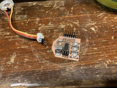
Unfortunately, the board broke while being transported across the country, so I'll have to upload a recording of the board playing music later :( |
|
|
After figuring out all of this PWM myself, I stumbled upon this great board that does multi-voice synthesis not using PWM but resistor math. Since this code be used for my final project where multiple guitar strings may be played simultaneously, I started working on a new version of the firmware that does multi-voice synthesis similarly. I got a couple general good ideas for wavetable synthesis from looking at this code: most importantly, my previous method using a timer interrupt to step through the wave table limited the granularity at which I could change the frequency, actually creating slightly off-pitch sounds. Brian's firmware uses a 16-bit incrementer and takes only the high 8 bits as the index of sample in the wavetable, allowing a higher precision and more faithful sound creation. I will update back when I've made more progress! | |