assignment
My final project will likely include some microcontroller. That microcontroller needs some code, and in order to flash the conroller, I could either buy this $93 in-circuit programmer or I could make my own with about $5 worth of materials!
This week, I followed Brian's comprehensive guide to making an in-circuit programmer. This involved milling the circuit board out of a copper plate adhered to some non-conducting plastic and then soldering the components onto my custom-milled board!
milling | |
|
Given the schematic for an already-routed circuit board (shown below), I carefully cut out the traces and then outline of my new in-circuit programmer. |
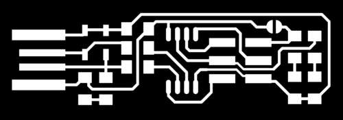
The copper traces to be cut out. 
The outline of the board to be cut through. |
|
This ended with a nice looking final product, that (as it appears) can plug straight into your computer's USB port! |
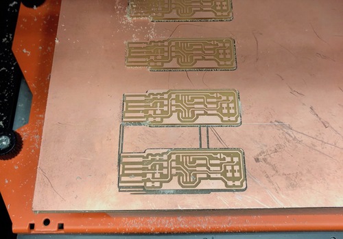
The fully milled boards. 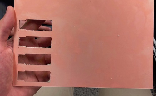
The outline left by four boards. |
soldering | |
|
After cutting out my board, I began the process of soldering these grain-of-rice-sized components... |
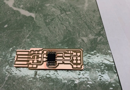
The first soldered (and largest) component. It's only downhill from here... 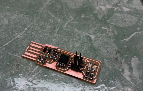
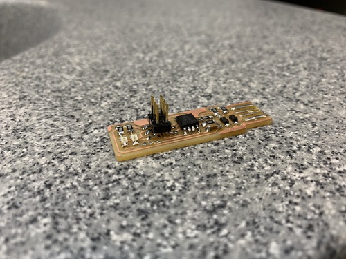
The fully soldered board. |
|
My new shiny board was now ready to be programmed (by an in-circuit programmer) in order to become a new in-circuit programmer! This will be a handy tool going forward as I start creating and routing my own complex electronics. |
|