Week 9 - Input Devices
This week, I worked on reading input from a piezoelectric sensor, which senses vibrations. The goal is to use it to detect strumming in my final project, for which I’m working on the strumming half of an electric guitar.
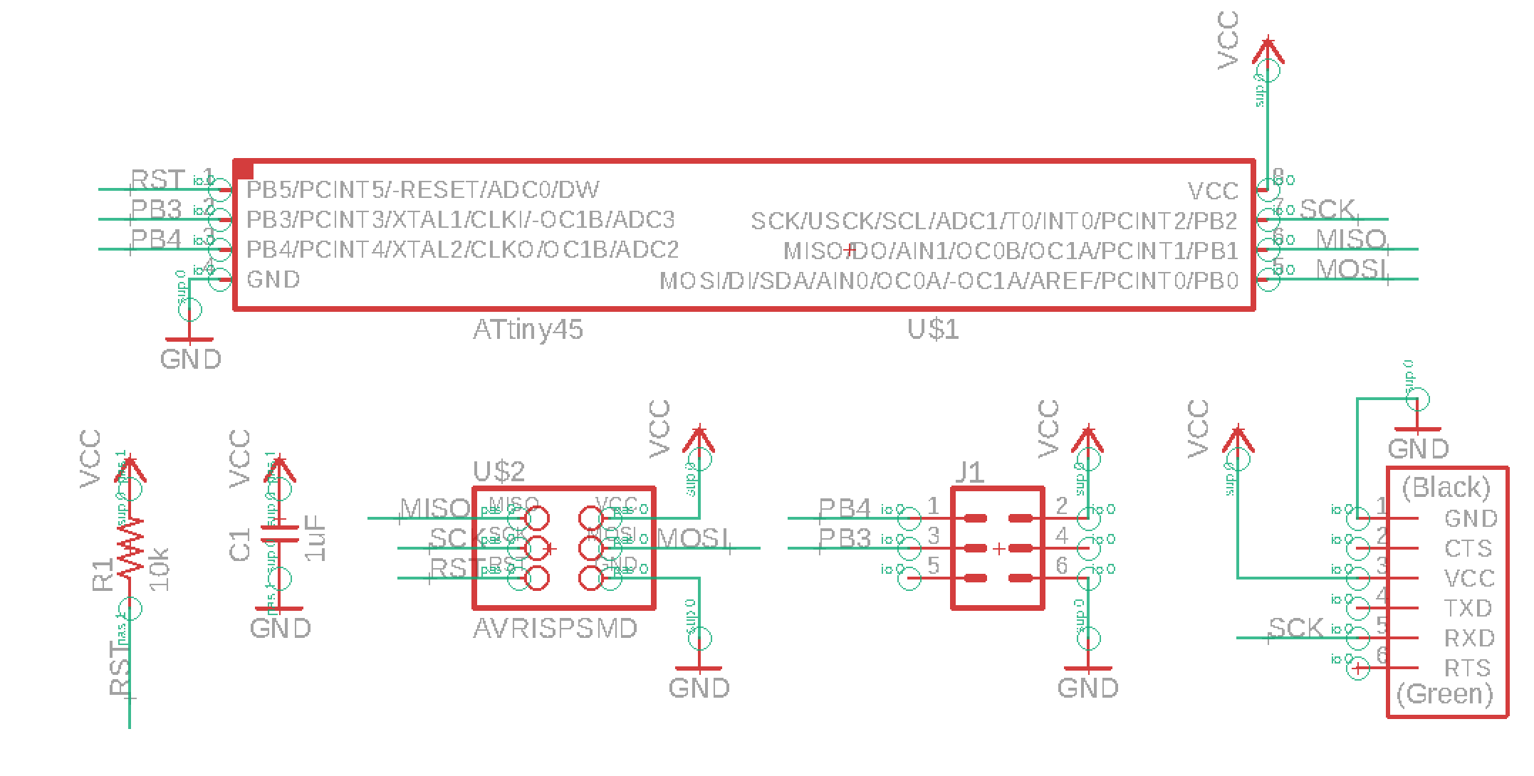
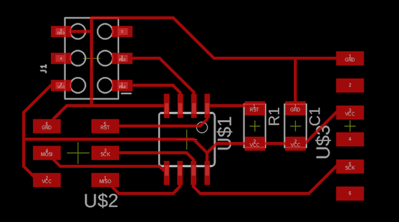
First, I made a generic board, with a six pin input that connects to VCC, GND, and two pins on the Attiny45. This is so I don’t have to create a completely new board everytime I want to experiement with an new sensor. This was heavily based on Neil’s boards.


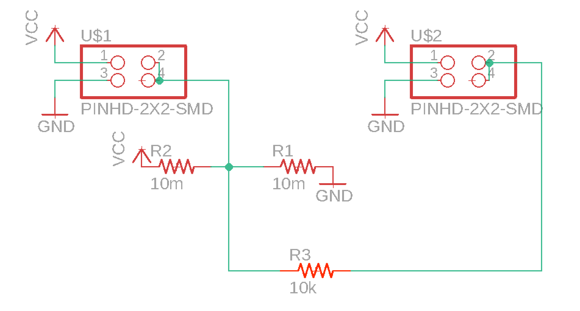
After consulting Gabe Miller’s project from 2015, I added in a voltage divider to make the output easier to read. I printed this onto a separate board, which I then connected to my main board.

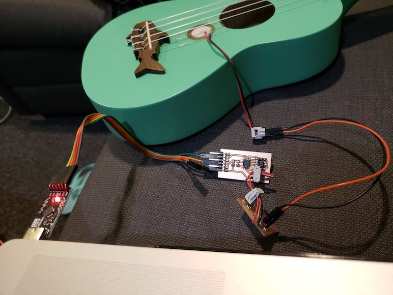
Here are all the components wired up:

I then programmed it, again working off of Neil’s example code. Here’s how I got the digital output from the piezo. I couldn’t figure out how to get the analog output, even though it seems super simple.
int main(void) {
  // main
  static char chrl;
  static char chrh;

  // set clock divider to /1
  CLKPR = (1 << CLKPCE);
  CLKPR = (0 << CLKPS3) | (0 << CLKPS2) | (0 << CLKPS1) | (0 << CLKPS0);

  // initialize serial pin
  set(serial_port, serial_pin_out);
  output(serial_direction, serial_pin_out);

  // init A/D
  ADMUX = (0 << REFS2) | (0 << REFS1) | (0 << REFS0) // Vcc ref
          | (0 << ADLAR) // right adjust
          | (0 << MUX3) | (0 << MUX2) | (1 << MUX1) | (1 << MUX0); // ADC3
  ADCSRA = (1 << ADEN) // enable
           | (1 << ADPS2) | (1 << ADPS1) | (1 << ADPS0); // prescaler /128

  // main loop
  while (1) {
    // send framing
    put_char(&serial_port, serial_pin_out, 1);
    char_delay();
    put_char(&serial_port, serial_pin_out, 2);
    char_delay();
    put_char(&serial_port, serial_pin_out, 3);
    char_delay();
    put_char(&serial_port, serial_pin_out, 4);
    char_delay();

    // initiate conversion
    ADCSRA |= (1 << ADSC);

    // wait for completion voltage analog -> digital
    while (ADCSRA & (1 << ADSC));

    // send result
    chrl = ADCL;
    put_char(&serial_port, serial_pin_out, chrl);
    char_delay();
    chrh = ADCH;
    put_char(&serial_port, serial_pin_out, chrh);
    char_delay();

  }
}
I read the serial output with a super simple python program:
import serial
import sys

prev_value = 0

def main():
    global prev_value

    # idle routine
    byte2 = 0
    byte3 = 0
    byte4 = 0
    ser.flush()
    while 1:
        # find framing
        byte1 = byte2
        byte2 = byte3
        byte3 = byte4
        byte4 = ord(ser.read())
        if ((byte1 == 1) & (byte2 == 2) & (byte3 == 3) & (byte4 == 4)):
            break
    low = ord(ser.read())
    high = ord(ser.read())
    value = (256 * high + low)
    if abs(value - prev_value) > 10:  # will only print if change is greater than threshold
        print(value)
    prev_value = value

#  check command line arguments
if (len(sys.argv) != 2):
    print "command line: hello.HC-SR04.py serial_port"
    sys.exit()
port = sys.argv[1]

# open serial port
ser = serial.Serial(port, 9600)
ser.setDTR()

while 1:
    main()
It works!
Next steps would be to figure out how to get the analog output, and see if it’s possible to differentiate between the different strings being plucked.
Files
board-outline.png
board-traces.png
divider-outline.png
divider-traces.png
piezo.c
piezo.py
Makefile